Introduction to NURBS modeling technology
Today I will show another technique of creating models with curves. We begin, as usual, with a little theory, we first consider the NURBS-curves, and then move on to the NURBS-surfaces. Next, try to do with NURBS-curves of some model. Well, in the final part we impose on the objects created by the materials.
Let's start with the theory ...
First decipher the acronym NURBS. NURBS - a Non-Uniform Rational B-Spline or in Russian non-uniform rational B-splines. NURBS-curves have one feature: they always have a smooth shape.In 3d max there are two types of NURBS-curves: P-curves and the CV-curves.
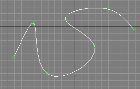
P-curve (point curves) - these curves are defined by the vertices lying directly on the curve. In fact, they are similar to regular splines.
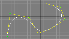
CV-curves (control vertices curves) - a form of such curves is given control vertices that lie on the auxiliary curve (shown yellow).
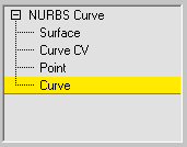
To create one of these curves, it is necessary to go to the tab Create tab, Shape, and then the drop-down list, select the NURBS Curves and click on one of the buttons depending on the type of curve:
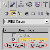
If you remove the checkbox next to the Start New Shape, then you proceed to create the selected curve.
Unlike Unlike conventional spline NURBS-curves can be created in multiple viewports, creating a flat and did not immediately volume curve. The truth must be admitted that, in this way to create something really complicated, it is necessary to have a very good spatial reasoning or do not attempt to create one. It is much easier, as is the case with conventional splines, change some hastily created piece.
NURBS-surface form of the NURBS-curves and, like the curves can be of two types: P-surface (point surfaces) and CV-surface (control vertices surfaces). As is not difficult to imagine these types differ from each other the same, the differences between two types of curves.
There are several ways to create a NURBS-surface.
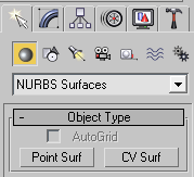
You can create a rectangular piece of NURBS-surface on the tab Create (Create-> Geometry-> NURBS Surfaces):
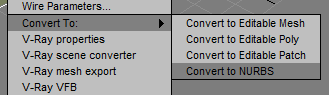
You can convert a NURBS-surface is generated in some other way an object. To do this, right-click on the object and choose from the menu Convert To: -> Convert to NURBS.
Finally, you can create a surface by combining multiple NURBS-curves. It is in this way we will use in the practical part of the lesson.
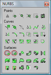
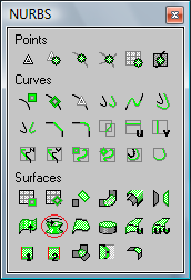
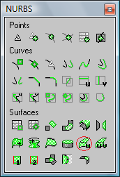
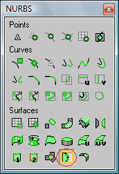
If you create a NURBS-curve or surface, and go to the tab Modify, then the panel will open with the tools NURBS:
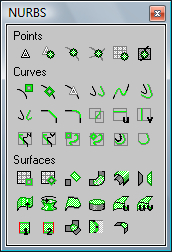
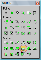
If the panel does not open, it can be accessed by pressing the NURBS Creation Toolbox:
This section of the socket is to control the peaks (Points), curves (Curves) and surfaces (Surfaces). Of greatest interest to us are the management tools surfaces, so we consider some of them.
Create CV Surface, Create Point Surface:
As is not difficult to guess from the name, the tools create both types of surfaces. These buttons are different from the buttons on the tab Create what started the surface will belong to the current object (will subobjects).
Create Blend Surface:
Creates a smooth transition between the two surfaces:
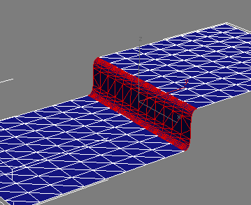
To use this tool must have two surfaces belonging to the same object. To create the surface after the choice of instrument should click on the edge of one surface (where the surface will begin created), then have to click on the edge of the second surface (where the surface will be created to end)
Create Mirror Surface:
Reflects the surface.
Create Extrude Surface:

Extrudes from the surface of the curve. For example, of such a curve:
You can extrude a surface:
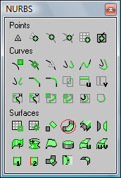
Create Lathe Surface:
Creates a surface of revolution, like the Lathe modifier of the lesson number 3
Create Cap Surface:
Creates a surface bounded by a closed curve. For example, to set up just above the surface, you can create a cover:
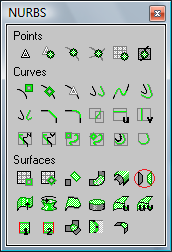
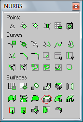
Create U Loft Surface:
Creates a surface of the U-loft of a set of parallel cross sections perpendicular to the longitudinal axis of the future facility. Learn more about this tool, you will learn the practical side.
Create UV Loft Surface:
Creates a surface UV-loft of the two teams open NURBS-curves. At the same must hold two rules:
- Curves of the same group must lie along one of the axes created by the body and to be parallel to each other;
- Ends of the curves from one group should be located at the extreme curves belonging to another group.
For example, we have two sets of curves (selected and not selected):
- Curves of the same group must lie along one of the axes created by the body and to be parallel to each other;
- Ends of the curves from one group should be located at the extreme curves belonging to another group.
For example, we have two sets of curves (selected and not selected):
Based on these curves we face:
Some of the other instruments will be considered in the practical part.
To conclude this theoretical section should clarify something else:
- NURBS-surface is always have a smooth shape. Therefore, the most logical to use for modeling objects flattened shape with no sharp edges.
- Implementation of NURBS-modeling in 3d max has always been a lot of criticism, he was too "buggy".Yet sometimes an object can be faster and better to create it using NURBS (hopefully soon you will see for yourself), so hush about this way of modeling correctly.
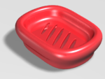
Creating a soap dish
I spent a crazy long time to figure out which object is modeled in this part. It was almost desperate to find the necessary combination of ease of creation and the maximum number of used instruments. And then one day in the bathroom my eyes fell on a bar of soap, and I realized that there was nothing better than to come up with still does not work, so today we will simulate a bar of soap :)
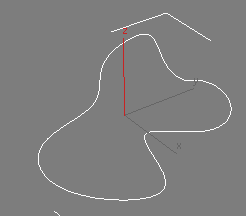
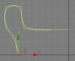
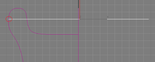
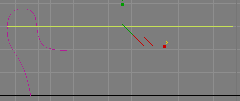
So start by creating an auxiliary line. It is desirable to establish it as a NURBS-curve (any type) to understand how they are created. But it does not matter and you can use a regular spline, for direct participation in the simulation to take this line still will not. I also used the CV-curve:
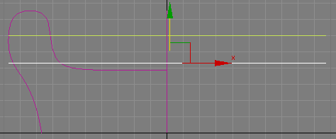
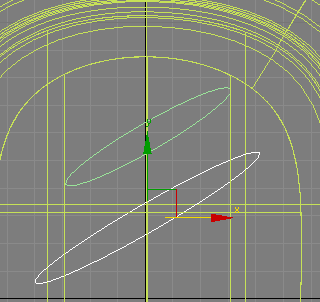
Now make a copy of this curve and rotate it 90 grudsov axis Z:
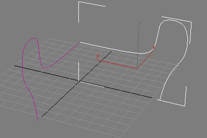
Next, move this curve slightly to the side:
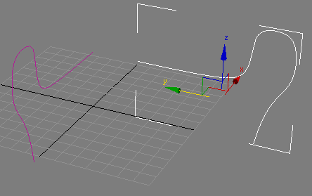
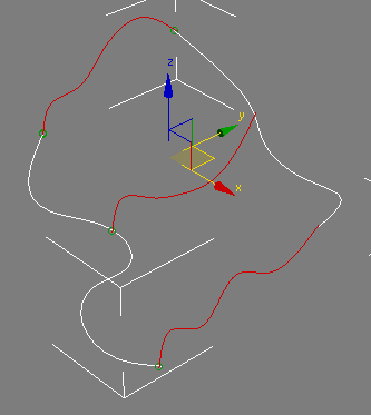
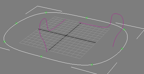
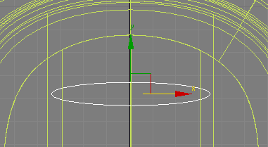
Thus, we have created as a limiting curves future soap dish. Now go to the top and create a P-curve in the form of an oval:
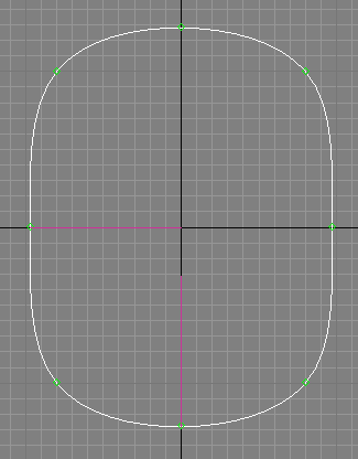
While this curve guided by a grid in the viewport to create the most symmetrical oval. Also note the location of auxiliary curves in relation to the oval: in a top view of the ends lie on the oval.
The result will be an oval, which is most likely you will have is this:
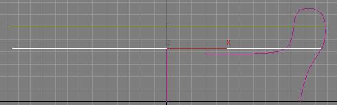
Need to raise the oval to the intersection with the auxiliary curves:
Now make a copy of the oval and drop it down:
Next, using the zoom tool (Select and Uniform Scale) promasshtabiruyte Oval X-axis to the intersection of c one of the auxiliary curves:
And then promasshtabiruyte Oval to the intersection of the other auxiliary curve c:
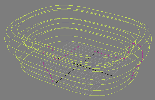
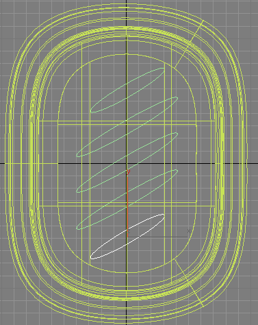
Make several copies of the oval and promasshtabiruyte them this way:
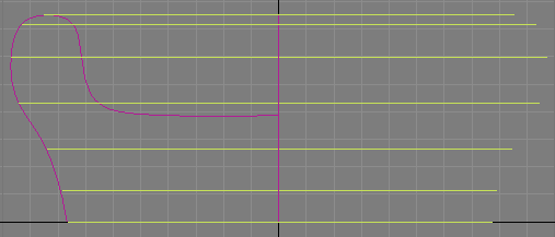
And then some more, with the intersection of the inner surface of the soap dish:
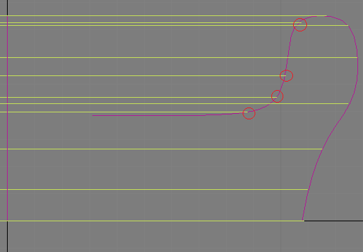
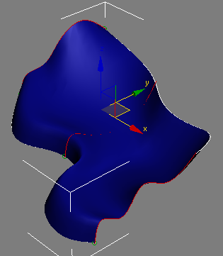
The result should look something like this:
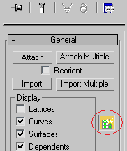
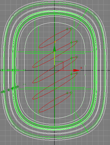
Now you need to connect all the created curves. To do this, select one of the curves on the Modify tab in the scroll General Find button Attach:
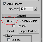
Click'll click this button and all the other curves. As a result, they are all united in one object.
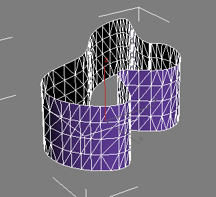
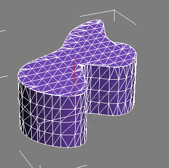
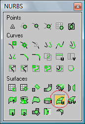
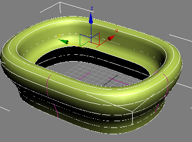
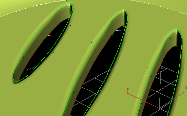
Next we create on the basis of these curves with the surface of the tool U-Loft. Select the curves, go to Modify tab on the panel NURBS tools, click Create U Loft Surface:
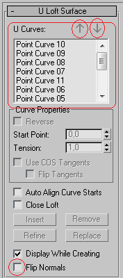
And start clicking on each curve in order, starting with the lowest and ending with internal curves. At the end of a right click.
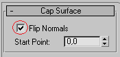
If you are in the process of creating a mixed sequence of random sequence of curves, then you can change them in the right pane. Perhaps the resulting surface will turn black, in this case, you have to put checkbox next to the Flip Normals:
If you are in the process of creating a mixed sequence of random sequence of curves, then you can change them in the right pane. Perhaps the resulting surface will turn black, in this case, you have to put checkbox next to the Flip Normals:
If everything was OK, then click the right mouse button again to fix the result. It should look something like this:
You can hide the two auxiliary curves, they are no longer needed. To do this, select them, click them, right-click and choose Hide Selection.
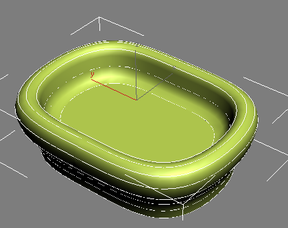
Next, you must patch up the holes in our soap dish, this tool select Create Cap Surface:
And click on the curve, which forms the bottom, and the undertaking of the curve in the soap dish:
If the resulting surface is black, put a checkbox next to the Flip Normals:
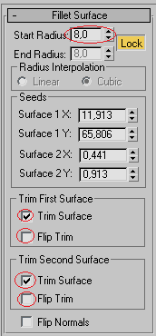
Now create the curve at the bottom of the soap dish, use this tool Create Fillet Surface:

Then click first on the lateral surface of the soap dish, and then on the bottom. Immediately after this it is necessary to put two rooks near Trim Surface. After that, may disappear one or both of the plane, in this case, you have to put checkbox next to the Flip Trim. Next, you must increase the radius of the bevel:
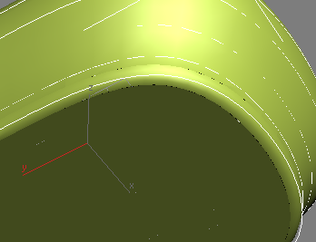
Click the right mouse button to fix the result:
Some of the splines can be converted to NURBS-curves, more importantly, that their composition was not the type of vertices Corner and Bezier Corner. Also in the NURBS-curves can be converted to four standard spline: Circle, Ellipse, Arc, and Star. It is this condition, we now use, create an ellipse on top form with a spline Ellipse:
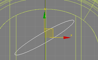
Then rotate the ellipse to 25-30 degrees:
Make a copy of the ellipse, and increase the parameter Length (or Width) tab, Modify, to increase the size of the ellipse:
Make a few copies:
Now select our soap-box and by clicking Attach, attach, these ellipses to it. Next, go into edit mode curves:
Select all the ellipses:
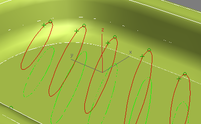
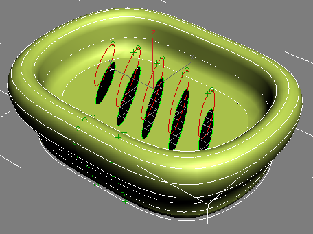
And lift them above the surface of the soap dish:
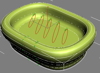
Return to the top view. Select the tool Create Vector Projected Curve:

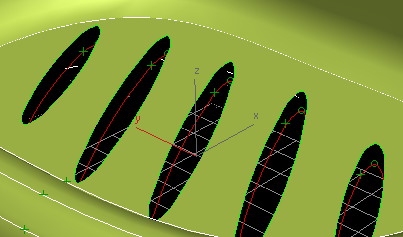
Use mouse on the first ellipse, then on the surface of the soap dish. Thus, it is necessary'll click all the ellipses. As a result of this action you will create a projection of the ellipses on the surface of the soap dish:
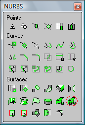
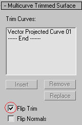
Next, activate the tool Create a Multicurve Trimmed Surface:
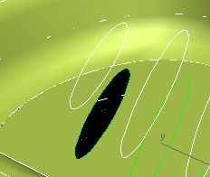
With this tool creates holes in NURBS-surfaces. Click on the surface of the soap dish next to the future of the hole, and then the ellipse are the projections on the surface. If after this has disappeared is not what was supposed to disappear, then put a checkbox next to the Flip Trim:
As a result, the hole should be able to:
The described method make the rest of the holes:
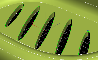
Now select the original ellipse and lower them slightly below the level of Holes:
With the already familiar to us Create U Loft Surface create a surface inside the holes:
The last finishing touch - the creation of the bevel in the same manner as the bevel on the bottom of the soap dish (using Create Fillet Surface):
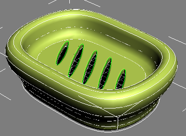
At the creation of the geometry of soap dishes can be considered complete:
Material Creation Soap
Let's create a simple material for the soap dish. Soap plastic, shiny, perhaps, may reflect a bit. You can find yourself features to a greater or lesser extent, reflects these characteristics, I also got this:
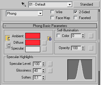
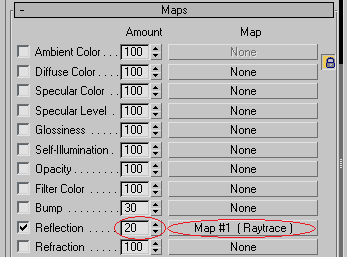
Notice the checkbox next to the 2-Sided, it allows you to apply (and display for renedere) material on both sides of the object. In the Maps rollout, I added a map and Raytrace Reflection with a value of 20 to create a small reflection on the surface:
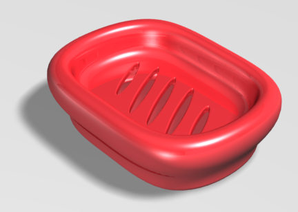
Finally got a soap dish:
No comments:
Post a Comment